dropdown menu

Showing posts with label VIO. Show all posts

POWERVM - VIOS INSTALL


VIO Install, Config (VIO Build)


These main steps will be followed:
- VIO Server creation on HMC
- VIO Server installation
- VIO Server configuration
- Network configuration (SEA, VLANs)
- Performance Tuning
- Additional things

-----------------------------------------------------------------

VIO Server creation on HMC 

CPU settings:
Shared, Uncapped weight: 255 (Proc. compatibility mode: Default)
Proc. Unit: min: 0.1, desired: 2,  max: number of CPUs in server (for smaller servers desired can be 1)
Virt. Proc: min: 1, desired: 6, max: number of CPUs in server (for smaller servers desired can be 3)

Memory settings:
min: 1 GB, Desired: 6 GB (it depends on how it will be utilized) max: 3x of desired

Adapters:
SAS RAID Adapter + USB + add only 1Gb Network to have correct device sequence later (after VIO install add 10Gb + FC adapter)

After VIO is created, in General Settings of VIO:
- Enable Mover Service Partition
- Enable Connection Monitoring (this is the connection between LPAR and HMC)
- Allow Perf. Information Collection

VIO IP address
Usually a 1GB adapter is used to login and install VIO, an IP address will be needed for that (it may need to be registered in DNS)

-----------------------------------------------------------------

VIO Server installation

There are more options for VIOS installation:
VIOS install from USB stick
VIOS install from HMC
VIOS install from NIM


VIOS install from USB stick: 
- Download ISO from IBM whose name contains the word flash
- Using software from Rufus (https://rufus.ie/) a bootable USB stick can be created
- After plug in USB stick in the Power server, and booting up VIOS LPAR, installation can be completed in HMC console


VIOS install from HMC
- Download DVD ISO from IBM
- Upload ISO images to HMC, using menu point on HMC: HMC Management --> Templates and OS Images
- During VIO activation on HMC, choose VIO install (takes more than an hour, at the end progress bar was hanging for 20 minutes)
- After installation completed accept License and close window


VIOS install from NIM

Prepare mksysb from ISO images:
- download DVD1 and DVD2 ISO images and copy to NIM
- mount ISO images: # loopmount -i dvdimage.v1.iso -o "-V cdrfs -o ro" -m /mnt2
- copy mksysb images from /usr/sys/inst.images to another directory (on Volume1 there are 2 mksysbs, on Volume 2 there is only one, during copy change name to avoid overwrite)
- combine 3 mksysb images into 1 (with command cat): # cat mksysb_image mksysb_image2 mksysb_image3 > vios2.2.3.4.mksysb

Create NIM resources and initiate restore:
- create mksysb res.: # nim -o define -t mksysb -a server=master -a location=/nim/mksysb/vios/gi_vios_2234.mksysb mksysb_gi_vios_2234
- create spot: # nim -o define -t spot -a server=master -a location=/export/spot -a source=mksysb_gi_vios_2234 spot_gi_vios_2234
- add VIOS IP to /etc/hosts (I used here newvio1 as a name)
- VIO NIM client: nim -o define -t standalone -a platform=chrp -a if1="find_net newvio1 0" -a netboot_kernel=64 -a connect=nimsh newvio1
- initiate restore: # nim -o bos_inst -a source=mksysb -a mksysb=mksysb_gi_vios_2234 -a spot=spot_gi_vios_2234 -a accept_licenses=yes -a no_client_boot=yes newvio1

SMS boot, configure IPs, restore mksysb....

-----------------------------------------------------------------

VIO Server configuration
(after installation is completed)

During first login:
give password for padmin:
accept conditions: a
oem_setup_env --> license -accept

Set IP and Hostname
# chdev -l en0 -a netaddr=172.23.88.67 -a netmask=255.255.254.0 -a state=up
# chdev -l inet0 -a route=0,172.23.88.1
# smitty hostname

Update VIO if needed:
# mount nimserver:/mgmt /mnt
$ updateios -accept -install -dev /mnt/VIO/VIO_3.1.0.10_Update
$ shutdown -restart
$ updateios -commit

Network files:
update resolv.conf with domain, search list and nameservers (root.staff, 644)
update netsvc.conf with "hosts = local, bind4" (root.system, 664)
update /etc/hosts with needed host entries

paging space:
(6 GB (remove: paging00 and  increase hd6 6GB, (12 pp with pp size 512MB))
# swapoff /dev/paging00
# rmps paging00
# chps -s 11 hd6

dump device
(set dump device: lv_dump00 (8 pp with pp size 512MB))
# lsvg -l rootvg
# sysdumpdev -l
# sysdumpdev -Pp /dev/sysdumpnull
# extendlv lg_dumplv 6
# chlv -n lv_dump00 lg_dumplv
# sysdumpdev -Pp /dev/lv_dump00

NTP
create missing files with touch:
$ ls -l /home/padmin/config
total 32
-rwxrw----    1 root     staff           730 Jan 06 06:46 ntp.conf
-rwxrw----    1 root     staff             9 Jul 01 2007  ntp.drift
-rwxrw----    1 root     staff             1 Jan 06 06:47 ntp.log
-rwxrw----    1 root     staff             1 Jan 06 06:47 ntp.trace

add missing things to ntp.conf:
# cat /home/padmin/config/ntp.conf:
server ntp.mydomain.com
driftfile /home/padmin/config/ntp.drift
tracefile /home/padmin/config/ntp.trace
logfile /home/padmin/config/ntp.log

uncomment  ntp line in /etc/rc.tcpip with vi:
start /usr/sbin/xntpd -a '-c /home/padmin/config/ntp.conf' "$src_running"

TZ (Time Zone)
# cat /etc/environment | grep TZ
TZ=Europe/Vienna

mirror rootvg
$ extendvg rootvg hdisk1
$ mirrorios -defer hdisk1
# bosboot -ad hdisk0
# bosboot -ad hdisk1

dumplv
We need 2 dumpdevices with correct name and size (one on hdisk0 one on hdisk1):
lv_dump00           sysdump    8       8       1
lv_dump01           sysdump    8       8       1

# mklv -t sysdump -y lv_dump01 rootvg 8  hdisk1; sysdumpdev -Ps /dev/lv_dump01

syslog
# vi /etc/syslog.conf
*.debug /var/log/messages  rotate size 1m files 10
auth.debug /var/log/auth.log  rotate size 1m files 10

# touch /var/log/messages; touch /var/log/auth.log; refresh -s syslogd

ssh key
Remove authorized_keys2 and create authorized_keys file with needed ssh pub key

add missing adapters
(make sure device name numbers are correct)
add 10GB network cards
add FC adapter

set recommended rules
$ rules -o diff -s -d (to view the differences between system and the recommended settings)
$ rules -o deploy -d (deploy the VIOS recommended default setting)

shutdown+activate LPAR
(make sure setting in profile are correct)
$ shutdown

-----------------------------------------------------------------

Network configuration:

In HMC Enhanced GUI Link aggregation and SEA can be fully configured there (no VIOS commands needed)
(this is good if adapter IDs are not important as we cannot specify those there)

Create LACP Etherchannel: 
Virtual Networks --> Link Aggr. Devices --> Add device (ieee8023ad)

Add virtual networks (VLANs)
(on HMC the Network Bridge means actually the SEA)
 Add a new VLAN: give a name, Bridged, 802.1Qtagging yes, then it will create a new Network Bridge (SEA): Bridge PVID 1, Large Send
When first VLAN is created an additional Virt. Network is also created automatically (with VLAN ID 1), it can be renamed if needed
Add additional VLANs

----------------------------------------
If manual configuration is needed in command line (dual VIOS setup):

Creating Virt. Eth. adapter on HMC (create as many as needed, then save in profile):
$ chhwres -r virtualio -m myp950 -p myvio01 -o a -s 100 --rsubtype eth -a "ieee_virtual_eth=1,port_vlan_id=4000,\"addl_vlan_ids=3029,1874\",is_trunk=1,trunk_priority=1"
$ chhwres -r virtualio -m myp950 -p myvio02 -o a -s 100 --rsubtype eth -a "ieee_virtual_eth=1,port_vlan_id=4000,\"addl_vlan_ids=3029,1874\",is_trunk=1,trunk_priority=2"
$ mksyscfg -r prof -m myp950 -p myvio01 -o save -n default --force
$ mksyscfg -r prof -m myp950 -p myvio02 -o save -n default --force

Creating Etherchannel (Link Aggregation, LACP) on VIOS: 
$ mkvdev -lnagg ent4 ent5 -attr mode=8023ad hash_mode=src_dst_port

Creating SEA on VIOS:
$ mkvdev -sea ent18 -vadapter ent12 ent14 ent16 ent17 -default ent12 -defaultid 4000 -attr ha_mode=auto
$ chdev -dev ent20 -attr ha_mode=sharing (first VIOS1 after VIOS2)
----------------------------------------

-----------------------------------------------------------------

Performance tuning:

increase buffers for Virt. Eth. adapters in SEA
chdev -l ent9 -a max_buf_huge=128 -P
chdev -l ent9 -a min_buf_huge=64 -P
chdev -l ent9 -a max_buf_large=128 -P
chdev -l ent9 -a min_buf_large=64 -P
chdev -l ent9 -a max_buf_medium=512 -P
chdev -l ent9 -a min_buf_medium=256 -P
chdev -l ent9 -a max_buf_small=4096 -P
chdev -l ent9 -a min_buf_small=2048 -P
chdev -l ent9 -a max_buf_tiny=4096 -P
chdev -l ent9 -a min_buf_tiny=2048 -P

same in 1 liner:
# chdev -l ent9 -a max_buf_huge=128 -P; chdev -l ent9 -a min_buf_huge=64 -P; chdev -l ent9 -a max_buf_large=128 -P; chdev -l ent9 -a min_buf_large=64 -P; chdev -l ent9 -a max_buf_medium=512 -P; chdev -l ent9 -a min_buf_medium=256 -P; chdev -l ent9 -a max_buf_small=4096 -P; chdev -l ent9 -a min_buf_small=2048 -P; chdev -l ent9 -a max_buf_tiny=4096 -P; chdev -l ent9 -a min_buf_tiny=2048 -P

largesend and large_receive
On VIO largesend was already turned on, and large_recieve was on "no", so this have to be changed to "yes" (online)
# chdev -l ent10 -a large_receive=yes

queue_depth for hdisks (if needed)
(num_cmd_elems for FC adapters should be already set by VIOS rules)
chdev -l hdiskX -a queue_depth=32 -P

-----------------------------------------------------------------

!!! Reboot!!!

-----------------------------------------------------------------

Additional things may needed:
- check LPAR profile (just to be sure config is OK)
- install additional device drivers
- install additional tools like rsync, screen, lsof...
- add VIO server to monitoring tool (like LPAR2RRD)
- set up crontab (for backup scripts ...)
- create a backup

-----------------------------------------------------------------

vNIC


vNIC adapter

The SR-IOV implementation on Power servers has an additional feature, it is called vNIC (virtual Network Interface Controller). vNIC is a type of virtual Ethernet adapter, that is configured on the LPAR. Each vNIC is backed by an SR-IOV logical port (LP) that is available on the VIO server.  The key advantage of placing the SR-IOV logical port on the VIO, that it makes the client LPAR eligible for Live Partition Mobility. (Although the backing device resides remotely, through a so called LRDMA (Logical Redirected DMA) technology, the vNIC can map its transmit and receive buffers directly to the remote SR-IOV logical port). 


The above picture shows that data is transferred from the memory of client LPAR to the SR-IOV adapter directly without being copied to the VIOS memory. 

vNIC configuration happens on the HMC in a single step (only in the Enhanced GUI). When adding a vNIC adapter to the LPAR, it will create all necessary adapters automatically on VIO (SR-IOV logical port, vNIC server adapter) and on LPAR (vNIC client adapter). From the user perspective no additional configuration is needed at VIOS side.

It is really just 1 step on the Enhanced GUI interface:  choose LPAR --> Virtual NICs --> Add Virtual NIC (choose a VIO server, capacity)
In addition, a Port VLAN ID (PVID) may be configured for an SR-IOV logical port to provide VLAN tagging and untagging.

on VIO:
$ lsmap -all -vnic
Name          Physloc                            ClntID ClntName       ClntOS
------------- ---------------------------------- ------ -------------- -------
vnicserver0   U8608.66E.21ABC7W-V1-C32897             3 vnic_lpar      AIX

Backing device:ent14
Status:Available
Physloc:U76D7.001.KIC9871-P1-C9-T2-S6
Client device name:ent1
Client device physloc:U8608.66E.21ABC7W-V3-C3

on client LPAR:
# lsdev -Cc adapter
ent0   Available  Virtual I/O Ethernet Adapter (l-lan)
ent1   Available  Virtual NIC Client Adapter (vnic)


Regarding LPM:
When doing LPM, target system must have an adapter in SR-IOV shared mode with an available logical port and available capacity on a physical port. Additionally if labels are correctly set on the SR-IOV ports, during LPM the good physical port will be automatically chosen depending on the names of the label.


-------------------------------

vNIC and Etherchannel (NIB)

If 2 vNICs are created, which are coming from different VIO servers, then high availability can be achieved by creating an Etherchannel on top of these (one adapter is active, the other is backup)

# lsdev -Cc adapter
ent0   Available  Virtual I/O Ethernet Adapter (l-lan)
ent1   Available  Virtual NIC Client Adapter (vnic)       <-- coming from VIO1
ent2   Available  Virtual NIC Client Adapter (vnic)       <-- coming from VIO2

After creating etherchannel (NIB, Network Interface Backup config) with an IP address, in kdb we can check status of vNIC adapters:

# echo "vnic" | kdb
 +-------------------------------------------------+
|       pACS       | Device | Link |    State     |
|------------------+--------+------+--------------|
| F1000A00328C0000 |  ent1  |  Up  |     Open     |
|------------------+--------+------+--------------|
| F1000A00328E0000 |  ent2  |  Up  |     Open     |
+-------------------------------------------------+


If VIO1 goes down:
59224136   0320144317 P H ent3           ETHERCHANNEL FAILOVER


# echo "vnic" | kdb
 +-------------------------------------------------+
|       pACS       | Device | Link |    State     |
|------------------+--------+------+--------------|
| F1000A00328C0000 |  ent1  | Down |   Unknown    |
|------------------+--------+------+--------------|
| F1000A00328E0000 |  ent2  |  Up  |     Open     |
+-------------------------------------------------+


-------------------------------


vNIC failover

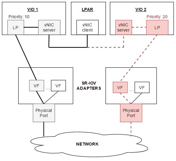
vNIC failover provides high availability solution at LPAR level. In this configuration, a vNIC client adapter can be backed by multiple logical ports to avoid a single point of failure. At any time, only one logical port is connected to the vNIC client (similar to a NIB configuration, but only 1 adapter exists at the LPAR). If the active connection fails, a new backing device is selected by the Hypervisor.

Prerequisites for vNIC failover:
- VIOS Version 2.2.5
- System Firmware Release 860.10
- HMC Release 8 Version 8.6.0
- AIX 7.1 TL4 or AIX 7.2


vNIC failover is achieved by monitoring the logical port (link status) and the VIOS health status, and reporting these to Power Hypervisor in regular heartbeats. In case of an error Hypervisor will switch traffic to the next backing device. 


Each backing device has a priority value (smaller number means higher priority) and a failover policy.

For example, when a vNIC is initialized, the Power Hypervisor selects the logical port with the highest priority (10 in the above picture). If that port goes down, the Hypervisor is notified, then selects, from the remaining (functional) backing devices, the logical port with the highest priority (20 in the above picture) as the next active backing device. Later, when the previously failed logical port recovers, the Hypervisor will switch back to the recovered port, if the priority failover policy has “auto priority failover” enabled; otherwise, it will stay there until the next failure occurs.

Creating vNIC failover configuration is simple:
Choose LPAR --> Virtual NICs --> Add Virtual NIC

The already existing vNIC adapters (without failover) do not need to be removed, those can be modified online.


With "Add entry" you can add new lines for backing devices (with priority value)

Auto Priority Failover: Enabled means, when the active backing device has not the highest priority (e.g. a higher priority device comes online), the hypervisor will automatically failover to this new device. (I have chosen "Disabled", as probably manual failback is better, in a convenient time.)

Failover Priority: Smaller number means higher priority. (During failure the next highest priority device will be provide network traffic.)


One small/side comment:
As documentation says, vNIC failover occurs if Link goes down, but in rare cases it can happen that Link status is up, however at switch side network is down (for example routing problem). In these rare cases no failover will happen (as Link status is still up), but at LPAR side network will be down. (If both Links would be active (as in a sort of LACP configuration, connected to different switches), or a ping possibility would be implemented, then this would not be a problem.)

==================================

How to check which VIO (and Adapter) provides the network traffic

On AIX entstat will show many details which VIO is currently utilized for the network:

# entstat -d entX | tail

Server Information:
        LPAR ID: 1
        LPAR Name: VIO1
        VNIC Server: vnicserver1
        Backing Device: ent17
        Backing Device Location: U98D8.001.SRV3242-P1-C9-T2-S4

==================================

SR-IOV

SR-IOV

SR-IOV (Single Root IO Virtualization) is a network virtualization technology. The basic idea is, that a physical device can have multiple virtual instances of itself, and these can be assigned to any LPARs running on the managed system. We have only 1 physical adapter, but each LPAR will think it has its own dedicated adapter. This is achieved by creating logical ports on top of the physical ports on the adapter. These ports will be exist in the Hypervisor (Firmware), so no VIOS is necessary. In order to see new SR-IOV menu points in HMC GUI, Firmware and HMC should be in a correct level.

Dedicated Mode - Shared Mode:
An SR-IOV capable adapter is either in dedicated mode or shared mode.
In dedicated mode, the adapter is owned by one LPAR. Physical ports of the adapter are owned by that partition. (Usual old config.)
In shared mode, adapter is owned by the Hypervisor. In this mode logical ports can be created and these can be assigned to any LPAR.

Logical Port (LP) - Virtual Function (VF)
A Virtual Function (VF) is a general term used by PCI standards. We can think of it as a slice of the physical port on the adapter. On IBM Power Systems, SR-IOV implements VFs as logical ports. A Logical Port (LP) is an I/O device created for a partition to access the Virtual Function on the adapter. When a Logical Port is created, the hypervisor will configure a virtual function on the adapter, and maps it to the Logical Port. These are in 1 to 1 relationship. (In general documentations the term VF is used many times, but during SR-IOV configuration on HMC, the term LP is used. In these standards another term, the Physical Function (PF) also exists, which we can think as a reference to the Physical Port.)

------------------------------------

Capacity (SR-IOV desired bandwidth)

During Logical Port (Virtual Function) creation the desired capacity need to be configured. This is similar to the Entitled Capacity (CPU) setting, just here % is used. The configured value is the desired minimum bandwidth in percentage. It is not capped, which means, if there is additional bandwidth that is not being used currently, it will be shared equally among all logical ports. Assignments are made in increments of 2 %  and total assignments for a single port can not exceed 100%. Capacity cannot be changed dynamically. (It is possible to change in profile and after profile activation is needed.)

So, if an LPAR needs, it will have % desired outgoing bandwidth. If additional outgoing bandwidth is available, any partition can use it. If a partition doesn’t need its minimum, that bandwidth is available to other partitions until the owning partition needs it. Capacity settings don’t have any influence on the incoming bandwidth.

------------------------------------

SR-IOV and LPM:


Picture shows an adapter with 2 physical ports, and one of those ports, is virtualized into 3 Logical Ports or VFs (yellow squares).

From a virtualization perspective, SR-VIO logical ports are seen as physical adapters at OS level, therefore operations like Live Partition Mobility are not supported when an SR-IOV logical port is configured on the partition (LPAR B).

If a Logical Port is part of a SEA (which bridge traffic from client partitions to the physical network) then client LPAR has only a Virtual Ethernet Adapter (LPAR A), so it can continue using Live Partition Mobility.

------------------------------------

SR-IOV and Link Aggregation

In an LACP configuration multiple primary SR-IOV logical ports are allowed. When LACP (IEEE802.3ad,) configured with multiple main logical ports, only SR-IOV logical ports can be part of the link aggregation and only 1 single logical port can be configured per physical port.

So, with LACP only one logical port per physical port can be used.
(The second configuration, with more than one logical port assigned to a physical port, will not work.)


To prevent users from adding a logical port to the physical port when LACP being used, you can set the logical port capacity to 100%.

------------------------------------

SR-IOV and Etherchannel (NIB):

In an active-passive configuration (Network Interface Backup), SR-IOV logical port can be primary (active) or backup (passive), or both. If more than one primary adapter is configured in an Etherchannel, then SR-IOV logical port cannot be a primary adapter. When an SR-IOV logical port is configured in an active-passive configuration, it must be configured to detect when to fail over from primary to the backup adapter. This can be achieved by configuring an IP address to ping.

------------------------------------

SR-IOV Configuration:

The main steps needed for SR-IOV:
- change adapter to shared mode
- configure physical ports
- configure logical ports

It is also important to meet necessary requirements: MC level, Firmware level, compatible SR-IOV adapter, Man. Sys. capabilities (SR-IOV capable: True)


Change adapter from Dedicated to Shared mode
Man. Sys --> HW Virtualized IO --> choose adapter --> Modify SR_IOV Adapter

This happens at Man. Sys. level, so adapter should not be assigned to any LPARs. If you check again after modification, you will see adapter will be owned by Hypervisor. It is possible to switch back to dedicated mode, just already configured logical ports must be de-configured prior to that.

------------------------------------

Physical port (PP) config: 
Man. Sys. --> HW Virtualized IO --> choose an adapter --> choose a port


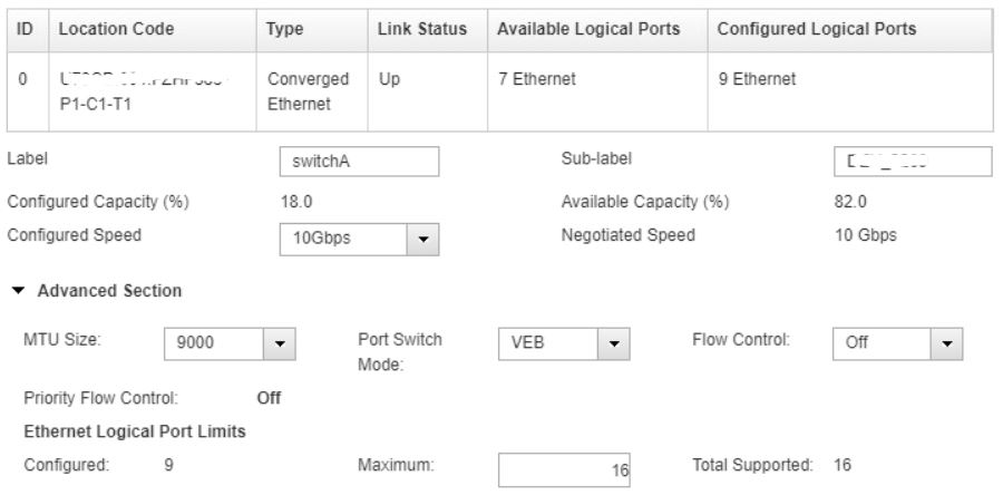
Label, Sub-label: These are helpful to identify a specific port.  Later during Logical Port creatition these help to identify better which physical port to use. During LPM HMC recognizes physical port labels (not Sub-labels) for vNIC devices. If set, HMC requires the same label to be present on the target system.

Configured Speed: 1Gbps, 10Gbps...

MTU Size: 1500, 9000. If the physical port is configured to MTU 1500 and a logical port attempts to use jumbo frames, oversized packets will get dropped.

Port Switch Mode: Virtual Ethernet Bridge (VEB) or Virtual Ethernet Port Aggregator (VEPA):
            VEB (This is the default): Bridging between logicalports (VFs) on the same physical port is done by the adapter.
            (Logical port to logical port traffic is not exposed to an external switch, lower latency.)
            VEPA: Bridging between logical ports on the same physical port is done by an external switch. 
            (Logical port to logical port traffic flows out to the external switch and then back. Switch can control traffic if needed.)

Flow Control: On or Off (default is off)
Flow control, controls data transfer to prevent a fast sender from over running a slow receiver. If the receiver has a heavy traffic load or if it has less processing power, then the sender transmits information at a faster rate than the destination can process it and in this case flow control can pause the traffic (or using priority flow control, it can selectively pause traffic on the link, for example only iSCSI or FCoE traffic only.) Modern computers can cache the data before the buffer fills up, so they do not need flow control.

Logical Port Limits: How many Logical Ports can be created on this Physical Port.
            Consider that desired capacity cannot exceed 100% physical port.
            For example if 4 Logical Ports with 25% have been created, then no additional LPs can be created on that physical port.

------------------------------------

Logical Port config:
Logical Port is mapped to an LPAR, so an LPAR has to be chosen before config.
choose an lpar --> HW Virtualized IO --> add port --> choose an adapter with a spec. physical port --> choose a port


Capacity: This is the desired minimum bandwidth of the port`s capacity.
          For 100/40GB adapters any value, for other adapters only even number can be used up to 100%.
          Logical ports can get more, if there is not used free bandwidth, and it is shared equally among all logical ports.
          Capacity settings do not apply to received traffic, only to transmitted traffic.
          Capacity cannot be changed dynamically, (calculate wisely during creation)
          Desired capacity cannot exceed 100% per physical port (this affects how many logical ports we can create)

Promiscuous: if the logical port will be assigned to a VIOS in a SEA, then enabling promiscuous mode is required.
         (Promiscuous mode can be enabled on only one logical port per physical port.)
          When promiscuous mode is enabled, the Allow All VLAN IDs and  Allow all O/S Defined MAC Addresses is the only option available.

MAC Address: The management console will auto assign the default MAC address unless a specific MAC address is set

MAC Address restrictions: (If Promiscuous is selected neither VLANs or MAC addresses can be restricted)
         Allow All – No restrictions on what MAC Addresses can be used.
         Deny All – The OS can only use the default MAC address
         Allow Specified – Set a list of MAC addresses that are allowed to be used by the OS. OS MAC config still needed in the OS.

VLAN restrictions: Restricts VLANs that the logical port device driver can use.
        (If Promiscuous is selected neither VLANs or MAC addresses can be restricted)
         Allow All– No restrictions on which VLANs can be used.
         Deny All– OS can not configure a VLAN ID. The OS will only receive packets that are untagged
         Allow Specified – Set a list of VLAN IDs that the OS is allowed to use for the LP. (VLANs still need to be configured in the OS)

         On Power9 if PVID is configured (other then 0), then VLAN Restrictions must be set to Deny All OS VLAN IDs.
         OS is only allowed to send frames untagged and receive untagged frames.

Port VLAN ID: Set a non zero PVID to have the adapter add a VLAN tag with this VLAN to all untagged transmit packets and strip the VLAN tag from receive packets. Received packets that have a match for this VLAN ID will be received by the OS as untagged packets.

Port VLAN ID (PVID) Priority: A value between 0 - 7 and it only applies if the PVID is set to a non zero value. (This is valid for specific adapters.)

------------------------------------

POWER9 Enhancements: Max Capacity
Max Capacity can be set to a Logical Port (in percentage), which means, the configured setting is the maximum percentage of the physical port's bandwidth. So the Logical Port still gets the desired value, but if free resources are available, it can go up to this setting. Platform firmware will provide a “best effort” to enable a maximum percentage to the logical port. It can be between 1 and 100, and the default is 100. It can be configured in HMC CLI and REST API (not possible in GUI) and cannot be changed dynamically.

To check if adapter supports max capacity: # lshwres -m my_p9 -r sriov --rsubtype adapter
…,custom_max_capacity_capable=1,…

Specify max capacity: # chhwres -m my_p9 -r sriov –rsubtype logport –id 2 -o a -a "adapter_id=1,phys_port_0,logical_port_type=eth,capacity=10,max_capacity=20"

List max capacity of SRIOV logical port: # lshwres -m alpfp094 -r sriov --rsubtype logport --level eth
…,max_capacity=20,…

Specify max capacity for vNIC:
chhwres -m my_p9 -r virtualio –rsubtype vnic –id 2 -o a -a "backing_devices=\"sriov/my-vios/1/1/2/10.00/20/60.0,sriov/my-vios2/2/1/3/8.00/40/80.0\""

Display max capacity of vNIC backing devices: # lshwres -m my_p9 -r virtualio –rsubtype vnic –filter "lpar_ids=2"
…backing_devices=”sriov/my-vios/1/1/2/27008014/10.0/10.0/20/60.0/60.0”…

Max capacity is displayed twice (60.0/60.0), the first one is the current max capacity, the second one is desired max capacity (also called original max capacity) and it's used for migration/remote restart to restore the original max capacity.

------------------------------------

Power9 Enhancements: Enable/Disable Logical Port
Similar to disabling/enabling a virtual Ethernet adapter or a virtual NIC adapter, we can now disable/enable a native SR-IOV Ethernet logical port. It is possible in HMC CLI only (not in GUI)

To disable:
chhwres -m <system name> -r sriov –rsubtype logport [-p <lpar name> | --id <lpar id>] -o d -a "adapter_id=<adapter_id>,logical_port_id=<logical_port_id>"

To enable:
chhwres -m <system name> -r sriov –rsubtype logport [-p <lpar name> | --id <lpar id>] -o e -a "adapter_id=<adapter_id>,logical_port_id=<logical_port_id>"

To display disable mode:
lshwres -m <system name> -r sriov –rsubtype logport –level eth –F logical_port_id, is_disabled

------------------------------------

After finishing it, on OS level a new adapter will be configured with VF in the name (cfgmgr may needed)

# lsdev -Cc adapter
ent0    Available 02-00 4-Port Gigabit Ethernet PCI-Express Adapter (e414571614102004)
ent1    Available 02-01 4-Port Gigabit Ethernet PCI-Express Adapter (e414571614102004)
ent2    Available 02-02 4-Port Gigabit Ethernet PCI-Express Adapter (e414571614102004)
ent3    Available 02-03 4-Port Gigabit Ethernet PCI-Express Adapter (e414571614102004)
ent4    Available 0C-00 PCIe3 4-Port 10GbE SR Adapter VF(df1028e21410e304)

# entstat -d ent4
...
...
VF Minimum Bandwidth: 24%
VF Maximum Bandwidth: 100%

VIO - VIRT. PROC.


VIRTUAL PROCESSORS AND ENTITLED CAPACITY

Processing Capacity
(Processing Units, Entitled Capacity)

Capacity Entitlement value is the time when you can access the core. Processing capacity can be configured in fractions of 0.01 processors. The minimum amount of processing capacity that has to be assigned to a micro-partition is 0.1 processors. (Starting with POWER7+ minimum is 0.05)

On the HMC processing capacity is specified in terms of processing units. (To assign a processing capacity representing 75% of a processor, 0.75 processing units are specified on the HMC.)

Once a micro partition is activated,  processing capacity is usually referred to as entitled capacity. This entitled capacity is reserved for that partition when it is started. The total entitled capacity of all the partitions configured on the system can never exceed the number of processors in that system.

------------------------------------------------
Capped and uncapped mode

Micro-partitions have  a specific processing mode that determines the maximum processing capacity given to them from their Shared-Processor Pool:

Uncapped mode: processing capacity can exceed the entitled capacity when resources are available in their Shared-Processor Pool (if there is competition amongst several partitions for unused processor capacity the uncapped weight will determine the sharing)
Capped mode: processing capacity can not exceed the entitled capacity

Uncapped Weight: Extra capacity is distributed between partitions in uncapped mode, by checking its uncapped weights. The higher the uncapped weight of a micro-partition, the more processing capacity the micro-partition will receive. (You must specify the uncapped weight when it is created.) The uncapped weight must be a whole number from 0 to 255. Default is 128. (If you set the uncapped weight at 0, the micro-partition will be treated as a capped partition.)

------------------------------------------------

Virtual Processor


A virtual processor is a representation of a physical processor that is presented to the operating system. A virtual processor cannot have a greater processing capacity than a physical processor. The capacity of a virtual processor will be equal to or less than the processing capacity of a physical processor. In terms of capacity, a physical processor can support up to 10 virtual processors.(From Firmware 760, 20 virtual processors.)

The Hypervisor uses a 10 ms dispatch cycle; each virtual processor is guaranteed to receive its entitled capacity of processor cycles during each 10 ms dispatch window. The Entitlement Capacitiy will be distributed equally between the Virtual Processors by the Hypervisor.

For example, if a logical partition has 1.60 processing units and 2 virtual processors, each virtual processor has 0.80 processing units. But the same LPAR with 4 virtual processors, each virtual processor has 0.40 processing units.

For example, if you have a partition with 0.50 processing units and one virtual processor, the partition cannot exceed 1.00 processing units. However, if the same partition with 0.50 processing units was assigned two virtual processors and processing resources were available, the partition could use an additional 1.50 processing units
The number of Virtual Processors can not be extended over 10X of the Entitled Capacaty. (From Firmware 760 it is 20X)
(If EC=0,5 then the maximum number of Virtual Processor can not be over 5, or from Firmware 760 over 10.)

------------------------------------------------

Desired, minimum and maximum values

When you set up a partition profile, you set up the desired, minimum, and maximum values you want for the profile. When a partition is started, the system chooses the partition's entitled processor capacity from this specified capacity range.

When starting a micro-partition, preference is given to the desired value, but this value cannot always be used because there may not be enough unassigned capacity in the system. In that case, a different value is chosen, which must be greater than or equal to the minimum capacity attribute. If the minimum capacity requirement cannot be met, the micro-partition will not start.
The maximum value is only used as an upper limit for dynamic operations. (adding RAM/CPU as a DLPAR operation).

------------------------------------------------

Processor Affinity (and processor binding):

Hypervisor always attempts to dispatch the virtual processor on to the same physical processor that it previously ran on. (To reduce contex switching...) This behavior is called processor affinity.  If this is not possible, the POWER Hypervisor will broaden its search out to other processors.

With AIX 6.1 TL5 and AIX 7.1 binding processors is available to application running in a shared LPAR  (an application process can be bound to a virtual processor).  PowerVM hypervisor (from firmware level 730) maintains three levels of affinity for dispatching, such as core, chip and node level affinity. By maintaining affinity at hypervisor level as well as in AIX, applications may achieve higher level affinity through processor bindings.

------------------------------------------------
Processor Folding:

Virtual processor folding puts idle virtual processors into a hibernation state so that they do not consume any resources.            
There are several important benefits of this feature: improved processor affinity, reduced POWER Hypervisor workload...
It will reduce the Physical Core usage (physc) at LPAR level.

------------------------------------------------

How to estimate the number of virtual processors per uncapped shared LPAR:

The first step would be to monitor the utilization of each partition and for any partition where the average utilization is ~100%, then add one virtual )processors. (use capacity of the already configured virtual processors before adding more

If the peak utilization is well below 50%, then look at the ratio of virtual processors to configured entitlement and if the ratio is > 1, then consider reducing the ratio.  (In any case if there are too many virtual processors configured, AIX can “fold” those processors.)

AIX monitors the utilization of each virtual processor and the utilization of an PLPAR, and if utilization goes below 50%, AIX will start folding down the virtual CPUs so that fewer virtual CPUs will be dispatched. (If utilization goes beyond 50% AIX starts unfolding virtual CPUs.)

------------------------------------------------

Considerations for Virtual Processor (VP) and Entitled Capacity:

- Lpars that require high performance (such as critical database) can be forced to get the best resources by activating the critical LPAR first prior to activating any other LPARs including VIO Server.

- The best practice for LPAR entitlement would be setting entitlement close to average utilization and let the peak addressed by additional uncapped capacity. 
(exceptions could be LPARs with higher priority)

- For each shared LPAR the number of VPs must be less than (or equal) to the number of cores of the shared pool

- Shared uncapped LPARS with too low VPs will not cover Production Need (VP number is a limit for uncapped LPARs)

- When AIX folding is turned off it can happen that PhysC (physical cores used) is high, but AIX shows high percentage of idle time. (This is because unused Virtual Processors are also assigned to cores, but they are not doing any work at all.)

------------------------------------------------

Checking how many Virtual Processors are active:

root@bb_lpar:/ # lparstat -i | grep Virt
Online Virtual CPUs                        : 2                               <--we have 2 virtual processors configured
Maximum Virtual CPUs                       : 8
Minimum Virtual CPUs                       : 1
Desired Virtual CPUs                       : 2

root@bb_lpar:/ # bindprocessor -q
The available processors are:  0 1 2 3 4 5 6 7                               <--this shows smt=4 active (4 threads/virtual processor)

root@bb_lpar:/ # echo vpm | kdb
...
   0     0  ACTIVE      0 AWAKE        0000000000000000  00000000  00
   1     0  ACTIVE      0 AWAKE        0000000000000000  00000000  00
   2     0  ACTIVE      0 AWAKE        0000000000000000  00000000  00
   3     0  ACTIVE      0 AWAKE        0000000000000000  00000000  00
   4     0  DISABLED    0 AWAKE        0000000000000000  00000000  00        <--4 lines are DISABLED, so 1 Virt. proc. is inactive (folding)
   5    11  DISABLED    0 SLEEPING     00000000515B4478  29DBE3CA  02
   6    11  DISABLED    0 SLEEPING     00000000515B4477  2C029174  02
   7    11  DISABLED    0 SLEEPING     00000000515B4477  2C0292A1  02

------------------------------------------------

POWERVM - VIOS UPDATE

VIOS update:


1. create backup:
    VIO Operating System (device mappings will be backed up as well?)
    backupios -file /mnt/backup                <--this will create nim_reources.tar file (in this are an mksysb,a spot dir...)
    backupios -file /mnt/backup -mksysb        <--this will create only an mksysb

    For NIM restore these are needed on NIM server:
        -create a resource from the mksysb (smitty nim -> administration -> resources -> define...)
        -create a spot resource from the mksysb (smitty nim -> administration -> resources -> define... -> source will be the mksysb)


    Device Configurations (Logical Devices, Virtual Devices, Device Attributes):
    (On 1.3.2 did not work)
    viosbr -backup -file /mnt/vio/vios1_devicebackup        <--creates a backup
    viosbr -view -file backup_1.tar.gz                      <--view in the backup file   

    (viosbr is needed if we restore to a different server. For the same server, backupios should be enough, as it contains mappings...)
    (For restore: viosbr -restore ....)

    savevgstruct                       <--saves other vgs
    restorevgstruct                    <--resore vgs to empty disk

    Other:
    lsmap -all, lsmap -all -net, lsmap -all -npiv...
    .profile file

2. remove interim fixes:
    # oem_setup_env                     <--from the VIOS command line
    # emgr -P                           <--list installed efix's (by label)
    # emgr -r -L                        <--for each additional efix listed, run to remove


3. do the update (as padmin)
    $ mount remote_machine:directory /mnt    <--mount the remote directory onto the Virtual I/O Server
    $ updateios -commit                      <--commit previous updates, by running the updateios command
    $ updateios -accept -dev /mnt            <--for updates -install is not needed
    ($ updateios -accept -install -dev /mnt  <--this will install new filesets as well)
    $ ioslevel                               <--verify update (it should indicate:ioslevel is now V1.5.2.1-FP-11.1)
    $ shutdown -restart                      <--to load all changes, reboot the VIOS as user padmin


------------------------------------------------

POWERVM - LPM

Live Partition Mobility

Live Partition Mobility (LPM) allows you to migrate partitions from one physical server to another while partition is running.

When all requirements are satisfied and all preparation tasks are completed, then HMC verifies and validates the LPM environment. This HMC function has the responsibility of checking that all hardware and software prerequisites are met. If this validation turns out to be successful, then partition migration can be initiated by using the HMC GUI or the HMC command-line interface.

Types of LPM:
- Active partition migration is the ability to move a running LPAR to another system without disrupting the operation of the LPAR.
- Inactive partition migration allows to move a powered-off LPAR from one system to another.
- Suspended partition migration allows to move a suspended LPAR

PowerVM allows up to 8 concurrent migrations per Virtual I/O Server and up to 16 per system.

-------------------------------------------

Mover service partition (MSP):
MSP is an attribute of the Virtual I/O Server partition. (This has to be set on HMC for the VIOS LPAR). Two mover service partitions are involved in an active partition migration: one on the source system, the other on the destination system. Mover service partitions are not used for inactive migrations.

-------------------------------------------

Virtual asynchronous services interface (VASI):

The source and destination mover service partitions use this virtual device to communicate with the POWER Hypervisor to gain access to partition state. The VASI device is included on the Virtual I/O Server, but is only used when the server is declared as a mover service partition.

--------------------------------------------

LPM overview:

1. Partition profile (active profile only) copied from source to target FSP.
2. Storage is configured on the Target.
3. Mover service partitions (MSP) is activated.
4. Partition migration started, copying memory pages (retransfer necessary pages)
5. When majority of memory pages has moved, system activated on target.
6. Final memory pages moved.
7. Cleanup storage and network traffic.
8. Storage resources are deconfigured from the source.
9. Partition profile removed from source server


Active partition migration involves moving the state of a partition from one system to another while the partition is still running. During the migration the memory of the LPAR will be copied over to the destination system. Because the partition is active, a portion of the memory will be changed during the transfer. The hypervisor keeps track of these changed memory pages, on a dirty page list and retransfers them as necessary.

Live Partition Mobility does not make any changes to the network setup on the source and destination systems. It only checks that all virtual networks used by the mobile partition have a corresponding shared Ethernet adapter on the destination system.

The time necessry for an LPM depends on the LPAR memory size, the LPAR memory activity (writes) and the network bandwith between source and destination. (dedicated LPM network with at least 1Gbps is recommended). When running 8 concurrent migrations through a Virtual I/O Server it is recommended to use a 10 Gbps network. (If there are high speed network transfers that can generate extra CPUs on VIOS side, this could also slow down LPM). If multiple mover service partitions are available on either the source or destination systems, it is a good idea to distribute the load among them.

A single HMC can control several concurrent migrations. The maximum number of concurrent migrations is limited by the processing capacity of the HMC and contention for HMC locks. If more LPMs are done concurrently, and the number of migrations grows, the setup time using the GUI can become long. In this case CLI could be faster.

--------------------------------------------------

Requirements for LPM:
(Most of them are checked by validation process)
(At the end of PowerVM Introduction and Configuration Redbook, there is a good list with pictures, where to check each.)

Hardware:
- Power6 or later systems
- System should be managed by at lease one HMC or IVM (if dual HMC, both on same level)
- If different HMCs are used for source and dest., both HMC should on the same network (so they can communicate with each other)
- Migration readiness of source and dest. (for example a server running on battery power is not ready, validation will check this)
- The destination system must have enough processor and memory resources to host the mobile partition


VIOS:
- PowerVM Enterprise Edition with Virtual I/O Server (or dual VIOSes) (version 1.5.1.1 or higher)
- Working RMC connection between HMC and VIOS
- VIOS must be designated as a mover service partition on source and destination
- VIOS must have enough virtual slots on the destination server
- If virtual switch is used, it has to be the same name on source and destination side
- VIOS on both system must have SEA configured to bridge to the same Ethernet network or vNIC can be used too
- VIOS on both system must be capable of providing access to all disk resources to the mobile partition
- If VSCSI is used it must be accessible by both VIO Servers (on source and destination systems)
- If NPIV is used physical adapter max_xfer_size should be the same or greater at dest.side (lsattr -El fcs0 | grep max_xfer_size)


LPAR:
- AIX version must be AIX 6.1 or above
- Working RMC connection between HMC and LPAR
- LPAR has a unique name (cannot be migrated if LPAR name is already used on destination server)
- Migration readiness (LPAR in crashed or failed state cannot be migrated, maybe a reboot is needed, validation will checkt his)
- No physical adapters may be used by the mobile partition during the migration
- No logical host Ethernet adapters
- LPAR should have a virtual Ethernet adapter or vNIC
- The LPAR we want to migrate cannot be a VIO Server
- The mobile partition’s network and disk access must be virtualized by using one or more Virtual I/O Servers
- All virtual networks of the LPAR (VLANs), must be availake on destination server
– The disks used by the mobile partition must be accessed through virtual SCSI, virtual Fibre Channel-based mapping, or both.
- If VSCSI is used no lv or files as backing devices (only LUNs can be mapped)
- If NPIV is used, each VFC client adapter must have a mapping to a VFC server adapter on VIOS
- If NPIV is used, at least one LUN should be mapped to the LPAR`s VFC adapter.
- LPAR is not designated as a redundant error path reporting partition
- LPAR is not part of an LPAR workload group (it can be dynamically removed from a group)
- LPAR is not using huge pages (for inactive migration it can use)
- LPAR is not using Barrier Synchronization Register (BSR) arrays (for inactive migration it can use)


--------------------------------------------------

Some additional notes:

- This is not a replacement for PowerHA solution or a Disaster Recovery Solution.
- By default the partition data is not encrypted when transferred between MSPs.
- Ensure that the logical memory block (LMB) size is the same on the source and destination systems.
  (In ASMI or "lshwres -r mem -m <managed system> --level sys -F mem_region_size")

--------------------------------------------------

lslparmigr -r sys -m <system>                        shows how many concurrent migrations are possible (num_active_migr._supported)
lslparmigr -r lpar -m source_sys                       list status of lpars (lpar_id will be shown as well)  
migrlpar -o v -t dest_sys -m source_sys --id 1         validation of lpar (id) for migration
echo $?                                                if return code is 0, validation was successful

migrlpar -o m -t dest_sys -m source_sys -p lpar1 &     migrating lpar
lssyscfg -r lpar -m source_sys -F name,state           show state

lslparmigr -r lpar -m source_sys -F name,migration_state,bytes_transmitted,bytes_remaining

--------------------------------------------------

nmon -> p (it will show details useful for migration)

--------------------------------------------------

Steps needed for LPM via HMC GUI:

1. choose LPAR on HMC -> Operations -> Mobility
2. choose Validate (Destination system name will be filled automatically or choose one) other settings can be leaved as it is -> Validate
3. after validation, choose slot IDs what will be used on destination system (change other settings if needed)
4. Migrate -> it will show a progress bar and inform you if it is done


--------------------------------------------------

HSCLA27C The operation to get the physical device location for adapter ...
on the virtual I/O server partition ... has failed.


Solution for me was to remove unnecessary NPIV adapters and mappings.
(I had NPIV configured for that LPAR, but no disk was assigned to that LPAR. After removing this NPIV config, LPM was successful.)

--------------------------------------------------

POWERVM - VSCSI STORAGE POOLS

VSCSI - Storage pools

In Virtual I/O Server (VIOS) Version 1.5, and later, you can create the following types of storage pools:

    * Logical volume storage pools (LVPOOL)
    * File storage pools (FBPOOL)

Like volume groups, logical volume storage pools are collections of one or more physical volumes. File storage pools are created within a parent logical volume storage pool and contain a logical volume containing a file system with files.

Logical volume storage pools store logical volume backing devices, file-backed storage pools, and the virtual media repository. File storage pools store file-backing devices.

In VIOS Version 2.2.0.11, Fix Pack 24, Service Pack 1, or later, you can use shared storage pools. Shared storage pools provide distributed storage access to all VIOS logical partitions in a cluster. Each cluster consists of one VIOS logical partition.

Storage pools are created and managed using the following commands:
chsp         Changes the characteristics of a storage pool
chbdsp       Changes the characteristics of a backing device within a storage pool
lssp         Displays information about a storage pool
mkbdsp       Assigns storage from a storage pool to be a backing device for a virtual SCSI adapter
mksp         Creates a storage pool
rmbdsp       Removes a backing device from its virtual SCSI adapter, and returns the storage back to the storage pool.
rmsp         Removes a file storage pool

By default, rootvg, which is a logical volume pool, is the default storage pool unless the prime administrator configures a different default storage pool.

Storage pools cannot be used when you assign whole physical volumes as backing devices:


When using file-backed virtual SCSI disks, you define storage-pool resources on the VIOS to contain the files that will serve as client disks.
When defining file-backed virtual disks, first use the mksp or mkvg command from the VIOS command-line interface to define a logical volume (LV) storage pool on the VIOS. An LV storage pool is a volume group in AIX LVM.

The next step in providing file-backed virtual disks is creating file-backed storage pools (or AIX LVs). You must use the mksp -fb command from the VIOS command line to create file-backed storage pools, and it doesn’t allow you to control placement of logical volumes in the volume group.

Once you create a file-backed storage pool, create a file-backed virtual disk for a client. Using the mkbdsp command, you create a file the client will use, and the virtual target device that links it to a virtual SCSI server adapter in the VIOS in one step.

The client attached to the server adapter will access the file on the VIOS as a SCSI disk. However, since the access is to a file that may be placed across multiple disks in the VIOS, you may see performance gains. Additionally, because it’s possible to create multiple file-backed disks in a single file-backed storage pool, there’s more flexibility available with this type of virtual SCSI disk than when using physical or logical volumes.

Performance gains are available when file-backed storage pools are defined across multiple physical volumes in a volume group (LV storage pool). For this reason, it’s recommended LV storage pools are defined across multiple physical volumes when possible.

However when we plan to use logical volumes as backing devices (not file-baked disks) keep this in mind:
Although logical volumes that span multiple physical volumes are supported, a logical volume should reside wholly on a single physical volume for optimum performance. To guarantee this, volume groups can be composed of single physical volumes.


POWERVM - VIRTUAL ETHERNET

Virtual Ethernet/Virtual Switch:

The Power Hypervisor has a feature to create Virtual Ethernet Network. This network is created by a Virtual Switch (which is part of the Hypervisor) and it  makes possible the communication between LPARs on the managed system without any physical devices. These are basically in-memory connections between LPARs through Virtual Ethernet Adapters.

When a Virtual Ethernet Adapter is created on the HMC a Virtual Ethernet switch port is configured at the same time, so the virtual port corresponds directly to the virtual Ethernet adapter. (There is no need to explicitly attach a virtual Ethernet adapter to a virtual Ethernet switch port it is done automatically by the Hypervisor. In fact both of them exist in the Hypervisor memory.)

------------------------------------

VLAN:

Virtual Local Area Network (VLAN) is a method to split up a physical network. This separation is achieved by configuring switch ports to be part of a VLAN and then tagging Ethernet packets with their VLAN information (VID=VLAN ID). The default VLAN ID for a switch port is the Port VID (PVID). (VLAN is described by the IEEE 802.1Q standard.)

The VLAN ID can be added to an Ethernet packet by the switch or it can be added by a VLAN-aware host. (VLAN-aware host could be an AIX server, where we have created a VLAN interface with "smitty vlan"). Ports on an Ethernet switch must therefore be configured with information indicating whether the host connected is VLAN-aware or VLAN-unaware.

VLAN unaware hosts: For VLAN-unaware hosts, a port is set up as untagged. This means the switch will tag all entering packets with the Port VLAN ID (PVID) and the switch will untag all exiting packets before delivery to the VLAN unaware host.(Untagged switch ports can be part of only one VLAN (PVID)).

VLAN aware hosts: Hosts that are VLAN-aware can insert and remove their own tags and can be members of more than one VLAN. These hosts are typically attached to ports that do not remove the tags before delivering the packets to the host, but will insert the PVID tag when an untagged packet enters the port.

A port will only allow packets that are untagged or tagged with VLANs of the port.

------------------------------------

Virtual Ethernet Adapter:

Virtual Ethernet adapters allow logical partitions within the same system to communicate without having to use physical Ethernet adapters. Within the system, these adapters are connected to a virtual Ethernet switch (which is basically in the Hypervisor), so TCP/IP communications over these Virtual Ethernet Adapters is routed through the server firmware. The system transmits packets by copying the packet directly from the memory of the sender logical partition to the receive buffers of the receiver logical partition without any intermediate buffering of the packet.

Virtual Ethernet adapters can be used without using the Virtual I/O Server, but the logical partitions will not be able to communicate with external systems. However, in this situation, you can use another device, called a Host Ethernet Adapter (or Integrated Virtual Ethernet), to facilitate communication between logical partitions on the system and external networks. The hardware MAC address of a virtual Ethernet adapter is automatically generated by the HMC when it is defined.

The POWER Hypervisor implements an IEEE 802.1Q VLAN style virtual Ethernet switch. Similar to a physical IEEE 802.1Q Ethernet switch it can support tagged and untagged ports. A virtual switch does not really need ports, so the virtual ports correspond directly to virtual Ethernet adapters that can be assigned to partitions from the HMC or IVM. (A virtual Ethernet switch port is configured when you configure the virtual Ethernet adapter on the HMC or IVM.)

Some Consideration:
- Maximum 256 virtual Ethernet adapters are permitted per partition.
- Maximum 20 VLANs are permitted on a Virtual Ethernet adapter (19 VIDs and 1 PVID).
- A system can support up to 4096 different VLANs
- A SEA can have maximum 16 virtual Ethernet adapters (with 20 VLANs on each)

Virtual Ethernet uses the system processors instead of off-loading that load to processors on network adapter cards. (It generates extra CPU)

------------------------------------


If you have one physical Ethernet adapter with device name ent0, which is connected to a tagged switch port with PVID=1 and VID=100, the administrator will generate an additional device name ent1 for the VLAN with VID=100 (smitty vlan). The original device name ent0 will represent the untagged Port VLAN with PVID=1. Ethernet interfaces can be put on both adapters: en0 would be stacked on ent0 and en1 on ent1, and different IP addresses will be configured to en0 and en1.

Dynamically adding or removing VLANs:
http://publib.boulder.ibm.com/infocenter/powersys/v3r1m5/index.jsp?topic=/p7hb1/iphb1_vios_managing_vlans.htm

Checking Virtual Ethernet Adapters and VLANs:
root@aix21: / # lsdev -Cc adapter
ent0   Available  Virtual I/O Ethernet Adapter (l-lan)
ent1   Available  Virtual I/O Ethernet Adapter (l-lan)

if it is an untagged port:
root@aix21: / # entstat -d ent0 | grep -i vlan
Invalid VLAN ID Packets: 0
Port VLAN ID:     1
VLAN Tag IDs:  None

if it is a tagged port:
Port VLAN ID:     1
VLAN Tag IDs:    23

(On HMC GUI, at the adapter properties these can be seen as well.)

------------------------------------

Adding/removing VLAN TAG dynamically:
(it will not add to profile)

adding (on HMC):
chhwres -r virtualio --rsubtype eth -m <man.sys.> -o s -p <LPAR> -s <adapter id> -a "addl_vlan_ids+=<VLAN TAG>"

removing (on HMC):
chhwres -r virtualio --rsubtype eth -m <man.sys.> -o s -p <LPAR> -s <adapter id> -a "addl_vlan_ids-=<VLAN TAG>"

------------------------------------

POWERVM - NIB, LA


Network Interface Backup (NIB)

Network Interface Backup (NIB) in the client partition can be used to achieve network redundancy when using two Virtual I/O Severs.

The client partition uses two virtual Ethernet adapters to create an EtherChannel that consists of one primary adapter and one backup adapter. The interface is defined on the EtherChannel. If the primary adapter becomes unavailable, the Network Interface Backup switches to the backup adapter.


A Link Aggregation of more than one active virtual Ethernet adapter is not supported (on the client -bb). Only one primary virtual Ethernet adapter plus one backup virtual Ethernet adapter are supported. To increase the bandwidth of a virtual Ethernet adapter Link Aggregation has to be done on the Virtual I/O Server .


Link Aggregation (on the VIO Server)

Link Aggregation is a network port aggregation technology that allows several Ethernet adapters to be aggregated together to form a single pseudo Ethernet adapter.

The main benefit of a Link Aggregation is that it has the network bandwidth of all of its adapters in a single network presence. If an adapter fails, the packets are automatically sent on the next available adapter without disruption to existing user connections. A link or adapter failure will lead to a performance degradation, but not a disruption.

802.3ad Link Aggregation do not support spanning across multiple network switches if the network switches are in a nonvirtualized state.. By using a backup adapter you can add a single additional link to the Link Aggregation, which is connected to a different Ethernet switch with the same VLAN. This single link will only be used as a backup.

(Activate Portfast on the network switches to allow faster failover time.)

Two variants of Link Aggregation are supported:
- Cisco EtherChannel (EC)
- IEEE 802.3ad Link Aggregation (LA)

While EC is a Cisco-specific implementation of adapter aggregation, LA follows the IEEE 802.3ad standard.


You could not, for example, attach a network interface en0 to ent0, as long as ent0 is a member of an EtherChannel or Link Aggregation.

Note: A Link Aggregation or EtherChannel of virtual Ethernet adapters is not supported. But you may use the Network Interface Backup feature of Link Aggregation with virtual Ethernet adapters.

A Link Aggregation with only one primary Ethernet adapter and one backup adapter is said to be operating in Network Interface Backup (NIB).

-----------------------

Limitations of IEEE 802.3ad Link Aggregation, 802.1Q VLAN tagging, and SEA:

- An 802.3ad Link Aggregation device has a maximum of eight active ports and eight standby ports.
- Set speeds of each link in a 803.3ad Link Aggregation device to a common speed (for example 1g/Full duplex)
- A virtual Ethernet adapter can support up to 20 VLANS (including the Port Virtual LAN ID (PVID))
- The IEEE 802.1Q standard supports a maximum of 4,096 VLANS..
- A maximum of 16 virtual Ethernet adapters can be associated to an SEA.
- A maximum of 256 virtual Ethernet adapters can be assigned to a single virtual server (VIOS as well)

-----------------------

If you plan to use 802.3ad Link Aggregation, your respective adapters must be cabled and the network switch ports must be configured for 802.3ad Link Aggregation. To create the Link Aggregation adapter use mkvdev (or cfgassist):
mkvdev -lnagg <entX> <entY> -attr mode=8023ad

------------------------


POWERVM - AME, AMS

Active Memory Expansion

Active Memory Expansion is the ability to expand the memory available to an AIX partition beyond the amount of assigned physical memory. Active Memory Expansion compresses memory pages to provide additional memory capacity for a partition. (It is a Power7 feature.)

AIX is currently the only opreating system that supports AME.

Planning considerations:
- Data that is already compressed will not compressed further with AME
- workloads that tend to frequently access only a small portion of memory will perform best with AME
- Active Memory Expansion will not compress file pages that are cached in memory
- Active Memory Expansion will not compress pinned virtual memory pages


AME config:
1. amepat <min>                <--run during peak times, i.e. amepat 120 will run for 2 hours and it will suggest an expansion factor
2. HMC -> profile -> memory        <--here the Act. Mem. Expansion factor should be ticked and the value entered
3. Partition Deactivate - Activate
4. lparstat -i                <--it will show the settings (once it has been enabled, the valuse can be changed dynamically (DLPAR))

Later if you want more fine tuning you can run 'amepat <min>' again.


------------------------------------
------------------------------------


Active Memory Sharing

Active Memory Sharing (AMS) enables the sharing of a pool of physical memory among partitions on a single IBM Power Systems server Power 6 or later, helping to increase memory utilization and drive down system costs.

The memory is dynamically allocated amongst the partitions as needed, to optimize the overall physical memory usage in the pool. Instead of assigning a dedicated amount of physical memory to each logical partition, the POWER Hypervisor constantly provides the physical memory from the Shared Memory Pool as needed.

Logical memory:
Quantity of memory that the operating system manages and can access. Logical memory pages that are in use may be backed up by either physical memory or a pool’s paging device.

For example, four logical partitions with 10 GB of dedicated memory each can be configured to share a memory pool of 40 GB, each with 15 GB of logical memory assigned.


Paging:
A Paging Virtual I/O Server is a partition that provides paging services for a shared memory pool and manages the paging spaces for shared memory partitions associated with a shared memory pool. A Virtual I/O Server enabled as a Paging Virtual I/O Server is designed to serve one shared memory pool.


This new configuration does not change the global memory requirements, and every logical partition can have the same amount of physical memory it had before. However, memory allocation is highly improved since an unexpected memory demand due to unplanned peak of one logical partition can be satisfied by the shared pool. In deed unused memory pages from shared-memory partitions can be automatically assigned to the more demanding one automatically

The hypervisor has to use a paging device to back up the excess memory that it cannot back up using the physical memory.

A paging device is required for each shared memory partition. The size of the paging device must be equal to or larger than the maximum logical memory defined in the partition profile. The paging devices are owned by a Virtual I/O Server. A paging device can be a logical volume or a whole physical disk. Disks can be local or provided by an external storage subsystem through a SAN.

Reserved storage device pool will be created automatically if AMS will be used, it will need for shared memory paging device.
(Ensure that PVIDs for paging devices for physical volumes set up by the HMC are cleared before use.)

-----------------------------------------

A Virtual Asynchronous Service Interface (VASI) is a virtual device that allows communications between the Virtual I/O Server and the hypervisor. In AMS environment, this device is used for handling hypervisor paging activity.

-----------------------------------------


POWERVM - COMMANDS

Commands

PowerVM Editions:
http://www-912.ibm.com/pod/pod

Under the VET code:
C2DBF2AD8D3427F6CA1F00002C20004110

-Express      0000
-Standard     2C00
-Enterpise    2C20

-----------------


VIOS service package definitions

Fix Pack
A Fix Pack updates your VIOS release to the latest level. A Fix Pack update can contain product enhancements, new function and fixes.

Service Pack
A Service Pack applies to only one (the latest) VIOS level. A Service Pack contains critical fixes for issues found between Fix Pack releases. A Service Pack does not update the VIOS to a new level and it can only be applied to the Fix Pack release for which it is specified.

Interim Fix
An Interim Fix (iFix) applies to only one (the latest) VIOS level and provides a fix for a specific issue.
-----------------

Virtual I/O Server is a special partition that is not intended to run end-user applications, and should only provide login for system administrators.  Virtual I/O Server allows the sharing of physical resources between supported AIX partitions to allow more efficient utilization and flexibility for using physical storage and network devices.


-----------------

User padmin:

Primary administrator on the VIO Server is the user padmin. It has a restriced shell (can't change home directory:/home/padmin) with vios commands.

The oem_setup_env command will place the padmin user in a non-restricted root shell with a home directory in the /home/padmin directory. The user can then run any command available to the root user. This is not a supported Virtual I/O Server administration method. The purpose of this command is to allow installation of vendor software, such as device drivers. (It is an environment to set up oem device drivers = oem_setup_env.)

By default the ioscli commands are not available for the root user. All ioscli commands are in fact calls of /usr/ios/cli/ioscli with the command as argument. (You see this if you list the aliases of the padmin user.)

You can use all ioscli commands as user root by appending /usr/ios/cli/ioscli. (/usr/ios/cli/ioscli lsmap -all)

You can set an alias:
 alias i=/usr/ios/cli/ioscli
 i lsmap -all

Typing exit, will return the user to the Virtual I/O Server prompt.

------------------------------------


/home/ios/logs/ioscli_global.trace shows history what was happening on the system (from commands point of view)

ioslevel                           shows vio server level
installios                         installs the Virtual I/O Server. This command is run from the HMC.
backupios                          creates an installable image of the root volume group (saves almost everything)
viosbr                             creates backups from user defined virtual device configs (saves only the mappings, virt. devices..)
viosbr -view -file <file name>     displays the contents of a backup file (whic was made before with viosbr)
savevgstruct                       it will make a backup of a volume group structure

lsgcl                              show history, what comands have been run on the vio server (gcl: global comand log)

cfgdev                             devices are recognized after runnig cfgdev
cfgassist                          on vio server as padmin brings up smitty style menu for doing several tasks
chkdev -dev hdisk4 -verbose        show if attached device can be migrated from physical adapter to virtual adapter (PHYS2VIRT_CAP.. -> yes)
chkdev -field NAME PHYS2VIRT_CAPABLE -fmt : show if disks can be used for vscsi (YES:yes, NO:no, NA:disk is already in use by VSCSI)

good overview of SEA sharing mode and adapters state:
entstat -all ent10 | grep -e "  Priority" -e "Virtual Adapter" -e "  State:" -e "High Availability Mode"

good overview of SEA and adapters VLAN id, MAC addres, Link status:
entstat -all ent10 | grep -e "(ent" -e "Type:" -e "Address:" -e "Link Status:" -e "Link State:" -e "Switch" -e "  ent"

lsdev                              lists all devices
lsdev -slots                       lists I/O slot information for built-in adapters (those are not hot-pluggable but DLPAR capable)
lsdev -virtual                     lists virtual devices
lsdev -type disk -virtual          lists virtual target devices (lists vscsi disks by the name what was given at mkvdev...-dev...)
lsdev -type adapter                same as lsdev -Cc adapter
lsdev -dev vhost0 -vpd             same as lscfg -vpl vhost0 in AIX (but on vio as padmin user lscfg does not work
lsdev -dev ent4 -attr              shows attributes of the devices (same as lsattr -El ent4)

chdev -dev fscsi0 -attr fc_err_recov=fast_fail dyntrk=yes -perm    changes the attributes (same as chdev -l fscsi0 -a fc_err_recov...)

lsmap -all                         lists all vscsi devices
lsmap -all -npiv                   lists npiv adapters (with slot numbers (aka adapter ID))
lsmap -all -net                    lists virtual ethernet adapters (with slot numbers (aka adapter ID))

lsmap -vadapter vhost0             shows infos about a specific vscsi adapter
lsmap -vadapter vfchost0 -npiv     shows infos about a specific npiv adapter
lsmap -vadapter ent11 -net         shows infos about a specific virtual ethernet device (with sea or physical devices will not work)

lsmap -all -field SVSA Physloc "Client Partition ID" VTD -fmt ":"                lists vscsi details
lsmap -all -npiv -field Name Physloc ClntID ClntName Status "FC name" -fmt ":"   lists npiv details
lsmap -all -vnic -field Name Physloc ClntID ClntName "Backing device" -fmt ":"   lists vnic details

lsvg -lv rootvg                    same as lsvg -l rootvg

lspv                               shows all available hdisk devices
lspv -free                         shows hdisks which are free to be used as backing devices
lspv -size                         shows hdisks with sizes

mkvdev -vdev hdiskX -vadapter vhostX -dev <vtd_name> create mapping between vhost and disk (vscsi disk assignment to vio client)
mkvdev -vlan ent9 -tagid 200       creates a vlan tagged interface over the ent9 interface (ent9 can be a SEA adapter)

rmvdev -vtd <vtd>                  removing connection between virt. target dev. (a physical dev. or an lv) and the virtual SCSI adapter
                                   (vtd can be found in lsmap output) (rmvdev -vdev <backing dev.> also works)
rmdev                              removes or unconfigures a device (rmvdev command can be replaced by rmdev, and rmdev is more universal)
rmdev -dev vhostX -recursive -ucfg put in defined state vhost adapter and its child devices (lsdev -dev vhostX -child)
                                   (-recursive: do actions on childdren as well, -ucfg: put only in defined state, do not delete device)
rmdev -pdev vhost13                deletes only childern devices of the given parent device (pdev) (vhostX will be still in available state)

vfcmap -vadapter vfchostX -fcp fcsX  mapping the virtual FC adapter to the VIO's physical FC
vfcmap -vadapter vfchostX -fcp       remove mappings of given vfchost adapter 

viosecure -firewall on -reload     enable firewall with default config (enables: https, http, rmc,ssh, ftp...)
viosecure -firewall view           display current firewall rules

license  -swma                     once helped, when vio commands did not want to work
remote_management                  this command enables VIOS to be remotely managed by a NIM master

/usr/ios/cli/ioscli ioslevel       run vios commands as root
viosvrcmd –m MSname –p VIOS1 –c "ioslevel" run vios commands from HMC CLI
------------------------------------

Info about virtual devices:

root@bb_lpar: /root # lscfg -l vscsi0
  vscsi0           U8204.E8A.0680E95-V3-C2-T1  Virtual SCSI Client Adapter

8204.E8A                           <--managed system type/model that contains this partition
0680E95                            <--serial number of the managed system
V3                                 <--partition id (on HMC LPAR id)
C3                                 <--slot number of this adapter (on HMC adapter id)

------------------------------------


mirroring vio server rootvg:
1. extendvg -f rootvg hdisk2        <--if pp limitation problem: chvg -factor 6 rootvg, then extendvg
2. mirrorios -defer hdisk2          <--mirror rootvg to hdisk2;  -defer is used, as no need to reboot since VIOS 1.5 :)
                                    (use the -f only if required, which will do a reboot without prompting you to continue)
3. bootlist -mode normal -ls        <--checking bootlist

------------------------------------

Debugging VIO problems:


I. truss:

$ oem_setup_env
# truss /usr/ios/cli/ioscli <failing_padmin_command> (or truss -feal /usr/ios/cli/ioscli <failing_padmin_command>)

---------

II. CLI_DEBUG=33

By exporting CLI_DEBUG=33, we can see which AIX command is used in the background of VIO command. After running that AIX command we can get more info.

For example:
1. mkvdev -vdev hdiskpower1 -vadapter vhost0 -dev testdisk         <--running this command gives not enough info about the problem
*******************************************************************************
The command's response was not recognized.  This may or may not indicate a problem.
*******************************************************************************

2. export CLI_DEBUG=33                                            <--exporting CLI_DEBUg=33

3. mkvdev -vdev hdiskpower1 -vadapter vhost0 -dev testdisk        <--running again, we can see which AIX command will be invoked
AIX: "lspv -l hdiskpower1 2>&1 | grep 0516-320"
AIX: "export LANG=C;/usr/sbin/pooladm -I pool querydisk /dev/hdiskpower1"
AIX: "/usr/sbin/lquerypv -V hdiskpower1"
AIX: "mkdev  -V hdiskpower1  -p vhost0  -l testdisk "             <--this command will be needed
*******************************************************************************
The command's response was not recognized.  This may or may not indicate a problem.
*******************************************************************************

4.oem_setup_env                                                   <--enabling root environment
5. mkdev  -V hdiskpower1  -p vhost0  -l testdisk                  <--running AIX command and it shows more detailed info
Method error (/usr/lib/methods/cfg_vt_scdisk):
        0514-012 Cannot open a file or device.


The solution was in this case, that I forgot to set no_reserve for the given disk on the other VIOS. The other VIOS already used this disk (with reservation) that is why I could not configure here because it was locked.

------------------------------------

Creating a client LPAR via VIO server:

planned devices for client LPAR:
1 virtual Ethernet
2 SCSI:
    -for virtual disk
    -for virtual optical device (cd)


1. find out what will be the client partition id (on HMC), because it will be needed when creating adapters for the new client LPAR
2. on VIO server (HMC) create virtual server adapters:
    - virtual Ethernet: for me it was enough for inter LPAR communicatio, so tagging is not needed (only remember PVID)
    - virtual SCSI for hdisk and optical device (cd): here the planned client partition id should be set
3. on VIO server configure the devices and mappings, after that 'cfgdev':
    -virtual Ethernet:
        set ip: chdev -l en19 -a netaddr=10.10.10.26 -a netmask=255.255.255.0 -a state=up

    -virtual SCSI for hdisk:
        map disk for rootvg: mkvdev -vdev hdisk45 -vadapter vhost1 -dev bb_lpar_rootvg

    -virtual optical device:
        create a file backed optical device, for iso images: mkvdev -fbo -vadapter vhost1
        copy the iso image to /var/vio/VMLibrary (lsrep)
        load the image into the vtopt0 device: loadopt -vtd vtopt0 -disk dvd.1022A4_OBETA_710.iso (lsmap -all will show it)

4. create client LPAR on HMC:
    partition id should be as planned (to match with the above created adapters)
    set processor, memory... phyisical I/O is not needed
    create virtual Ethernet and SCSI (it should be untagged as created on VIO Server with the same PVID)
    create SCSI adapter: 1 is enough for disk and optical device
    LHEA is not needed and other settings were not changed

5. activate profile
    go into SMS -> choose cdrom -> install AIX

6. on the new client LPAR
    set ip, hostname, routing...
    set ip: chdev -l en0 -a netaddr=10.10.10.25 -a netmask=255.255.255.0 -a state=up
   
    check ping from vio, then ssh is possible to new LPAR

------------------------------------

Network Time Protocol config:

1. vi /home/padmin/config/ntp.conf                 <--edit (or create) ntp.conf file as padmin (maybe root will need access to file as well)

    content should look like this:
    server ptbtime1.ptb.de
    server ptbtime2.ptb.de
    driftfile /home/padmin/config/ntp.drift
    tracefile /home/padmin/config/ntp.trace
    logfile /home/padmin/config/ntp.log

2. startnetsvc xntpd                               <--start xntpd daemon
3. cat /home/padmin/config/ntp.log                 <--check log for errors
    if you see this:
    time error 3637.530348 is way too large        <--if difference between local and timeserver time is too large synchroniztaion cannot occur

4. chdate 1206093607                               <--change clock manually
    Thu Dec 6 09:36:16 CST 2007

5. cat /home/padmin/config/ntp.log:
                <--check log again
    synchronized to 9.3.4.7, stratum=2

6. ps -ef | grep ntp                               <--it should show /home/padmin/config/ntp.conf (not /etc/ntp.conf)
    root  4390928  2818268  0 14:46:11 - 0:00 /usr/sbin/xntpd -x -c /home/padmin/config/ntp.conf

------------------------------------

I/O hosting requires a hosting partition - boot not permitted
exit called ok

This happened with me when I created an AIX LPAR, but a VIO image was installed on the disk, where I wanted to boot from.
(When there is a mismatch between the LPAR type and the booting image this error will pop up....I guess.)